

Overview
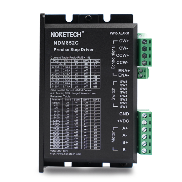
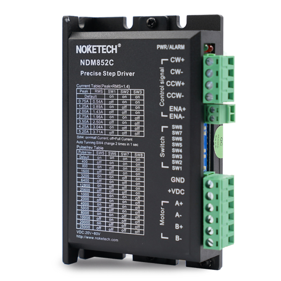
NDM852C is a digital two pluse two-phase hybrid stepper motor drive launched by Noketech, which could receive two pulse control signal. It adopts the latest DSP technology of Ti, and taking advanced digital filtering technology, anti-resonance technology and real-time precision current control technology to make it realize precise smooth operation, extra low noise . It’s especially suitable for semiconductor, electronic processing equipment, laser processing, medical equipment and small CNC equipment.
Suitable for:42/57/60 series two-phase hybrid stepping motor.
Parameter setting switch description
1)Working (dynamic) current setting
output peak current | output average current | SW1 | SW2 | SW3 |
Default | on | on | on | |
0.75A | 0.54A | off | on | on |
1.25A | 0.89A | on | off | on |
2.0A | 1.43A | off | off | on |
2.75A | 1.96A | on | on | off |
3.5A | 2.50A | off | on | off |
4.25A | 3.04A | on | off | off |
5.2A | 3.71A | off | off | off |
2)Quiescent (static) current setting
Static current can be set by SW4 DIP switch, on means that static current is the half of dynamic current, off means that the quiescent current is the same as the dynamic current.
In general use, to reduce heat generation of the motor and the drive and improve its reliability, SW4 should be set to on. About 0.4s after the pulse train stops , the current is automatically reduced to about half (60% of the actual value), and the calorific value is theoretically reduced to 36%.
3)Micro step setting
NDM852C is a precision two-phase hybrid stepping drive, which can provide a maximum of 512 subdivision settings, the specific settings are shown as below:
Steps/REV | SW5 | SW6 | SW7 | SW8 |
Default | on | on | on | on |
400 | off | on | on | on |
800 | on | off | on | on |
1600 | off | off | on | on |
3200 | on | on | off | on |
6400 | off | on | off | on |
12800 | on | off | off | on |
25600 | off | off | off | on |
1000 | on | on | on | off |
2000 | off | on | on | off |
4000 | on | off | on | off |
5000 | off | off | on | off |
8000 | on | on | off | off |
10000 | off | on | off | off |
20000 | on | off | off | off |
25000 | off | off | off | off |
Typical Wiring Case
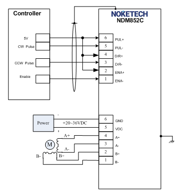
The following drawing is the wiring diagram of the motor with parallel connection when common anode control is adopted. When the control signal of the controller adopts 24V, 2K 1/4W current limiting resistance needs to be added on the control signal cable, or order NDM852C-24 directly which has built-in current limiting resistance.

NDM852C typical wiring digram
Electrical, Mechanical and Environmental Indicators
1.Electrical indicator
Description | NDM852C | |||
Min. | Typical | Max. | Unit | |
Output current | 0.5 | - | 5.2 | A |
Working voltage | 20 | 48 | 80 | VDC |
Control signal input current | 7 | 10 | 16 | mA |
Pulse frequency | 0 | - | 200 | kHz |
Insulation resistance | 500 | MΩ | ||
Note: The control pulse frequency can be adjustable according to user application requirements. The maximum control pulse signal that can be received is 1MHz.
2. Using environment and parameters
Cooling method | Free cooling or forced air cooling | |
Using environment | Places | Do not install it near other hot equipment.. Please avoid the places with dust, oil, corrosive gas, high humidity and strong vibration, combustible gas and conductive dust are prohibited. |
Temperature | 0-50℃ | |
Humidity | 40-90%RH | |
Vibration | 5.9m/s2MAX | |
Storage temperature | -20℃~80℃ | |
Weight | 220g | |
3.The way to improve heat dissipation
1)The reliable working temperature of the drive is usually within 60℃, and the working temperature of the motor is within 80℃.
2) To reduce the heat of the motor and drive, it is recommended to select the automatic half-current mode
when using, that he current decreases by half automatically when the motor stops.
3)When installing the driver, please install it vertically and sideways, so that the heat sink teeth forms strong air convection; when necessary, install a fan near the drive for better heat dissipation, to ensure that the drive works within a reliable operating temperature range.
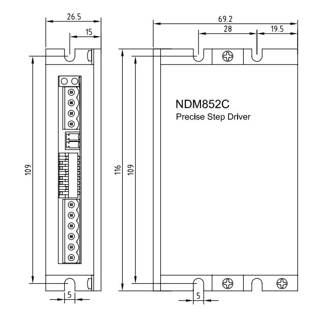
Mechanical installation drawing (unit: mm)
