-
産品描述
-
電(diàn)氣參數
-
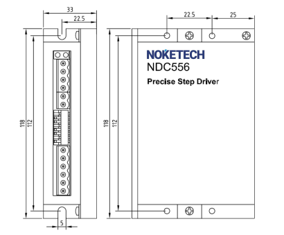
安裝尺寸
-
應用案例
Overview
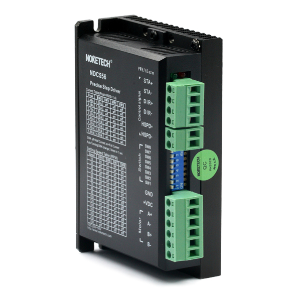
NDC556 is a digital stepping drive for 42/57 two-phase hybrid stepping motor speed regulation applications that developed by Noketech. The user can set the speed through the DIP switch and has the return double speed control function. Applicable fields: laser, assembly line, convenoy, intelligent logistics etc.
Parameter setting switch description
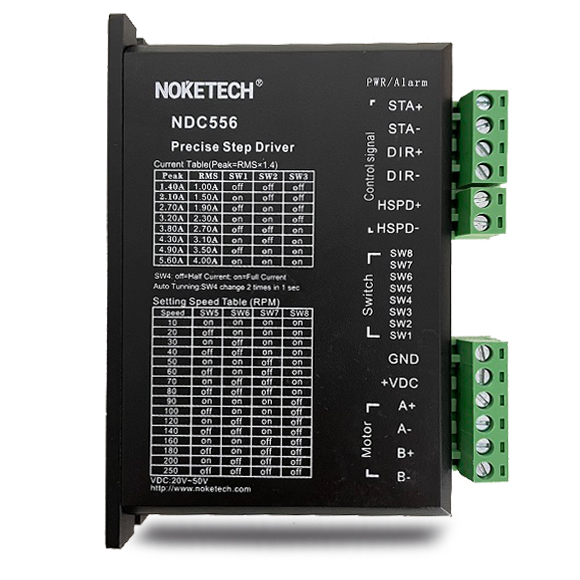
1) DIP switches SW1-SW3 set the output current of the drive, as shown in the table below:
output peak current | Out average current | SW1 | SW2 | SW3 |
1.4A | 1.0A | off | off | off |
2.1A | 1.5A | on | off | off |
2.7A | 1.9A | off | on | off |
3.2A | 2.3A | on | on | off |
3.8A | 2.7A | off | off | on |
4.3A | 3.1A | on | off | on |
4.9A | 3.5A | off | on | on |
5.6A | 3.0A | on | on | on |
2) DIP switches SW5-SW8 set the motor running speed, as shown in the table below:
Speed RPM | SW5 | SW6 | SW7 | SW8 |
10 | on | on | on | on |
20 | off | on | on | on |
30 | on | off | on | on |
40 | off | off | on | on |
50 | on | on | off | on |
60 | off | on | off | on |
70 | on | off | off | on |
80 | off | off | off | on |
90 | on | on | on | off |
100 | off | on | on | off |
120 | on | off | on | off |
140 | off | off | on | off |
160 | on | on | off | off |
180 | off | on | off | off |
200 | on | off | off | off |
250 | off | off | off | off |
3) DIP switches SW5-SW8 set the motor running speed, as shown in the table below:
Static current can use SW4 DIP switch to set up, on means Static current is the half of dynamic current, off means that the quiescent current is the same as the dynamic current. In general use, SW4 should be set to on to reduce the heat of the motor and drive and improve the reliability. About 0.4s after the pulse train stops , the current is automatically reduced to about half (60% of the actual value), and the calorific value is theoretically reduced to 36%.
Typical wiring diagram
The standard type of NDC556 adopts 24VDC control signal interface. When the controller is a PLC, it can directly connect the control signal without adding a current limiting resistor. In practical applications, the most typical application method is to use the common anode wiring method as shown in the following drawing:
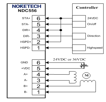
Typical wiring digram of NDC556
However, the control signal of NDC556 adopts the optical isolation mode, and the control signal can also be connected in differential mode or common cathode wiring mode according to the user application requirements, as shown in the following drawing:
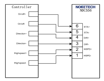
Typical wiring diagram when the controller
adopts 24VDC differential control mode
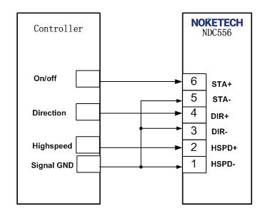
Typical wiring diagram when the controller
adopts 24VDC common cathode wiring
Note: If the signal output by the controller is 5VDC signal in the actual application, please order
NDC556-5; if you have other application requirements, please contact Noketech.
Electrical, Mechanical and Environmental Indicators
1. Electrical indicator
Description | NDC556 | |||
Min. | Typical | Max. | Unit | |
Output current | 1.4 | - | 5.6 | A |
Working voltage | 20 | 24/36 | 50 | VDC |
Control signal input current | 7 | 10 | 16 | mA |
Pulse frequency | 0 | - | 200 | kHz |
Insulation resistance | 500 | MΩ | ||
2. Using environment and parameters
Cooling method | Free cooling or forced air cooling | |
Using environment | Places | Do not install it near other hot equipment.. Please avoid the places with dust, oil, corrosive gas, high humidity and strong vibration, combustible gas and conductive dust are prohibited. |
Temperature | 0-50℃ | |
Humidity | 40-90%RH | |
Vibration | 5.9m/s2MAX | |
Storage temperature | -20℃~80℃ | |
Weight | 220g | |
3. The way to improve heat dissipation
1)The reliable working temperature of the drive is usually within 60℃, and the working temperature of the motor is within 80℃;
2) In order to reduce the heat of the motor and drive, it is recommended to select the automatic half-current mode when using that the current decreases by half automatically when the motor stops.
3)When installing the driver, please install it vertically and sideways, so that the heat sink teeth forms strong air convection; when necessary, install a fan near the drive for better heat dissipation, to ensure that the drive works within a reliable operating temperature range.
Mechanical installation drawing (unit: mm)
