 Home > Read stepper motor in one article
 Read stepper motor in one article
Category:Products News Publication date:2022-07-21 Article From:admin
Stepping motor is also called pulse motor, it is a kind of induction motor, involving many professional knowledge of machinery, electrical machinery, electronics and computer. As an executive element, stepping motor is one of the key products of mechatronics and is widely used in various automation control systems. With the development of microelectronics and computer technology, the demand for stepper motors is increasing day by day, and they are applied in various fields of national economy.
What is a stepper motor
Stepping motor is an actuator that converts electrical pulses into angular displacement. It converts electrical pulse signals into angular displacement or linear displacement. It is the main executive element in modern digital program control systems and has a wide range of applications.
The structure and working principle of stepping motor
Usually the rotor of a motor is a permanent magnet. When current flows through the stator winding, the stator winding generates a vector magnetic field. The magnetic field will drive the rotor to rotate by an angle, so that the pair of magnetic field directions of the rotor are consistent with the magnetic field directions of the stator. When the vector magnetic field of the stator rotates by an angle. The rotor also rotates an angle with the magnetic field.
Each time an electric pulse is input, the motor rotates one angle to move forward. The angular displacement it outputs is proportional to the number of input pulses, and the speed is proportional to the pulse frequency. Change the sequence of winding energization and the motor will reverse. Therefore, the number of pulses, the frequency and the energization sequence of each phase winding of the motor can be used to control the rotation of the stepper motor.
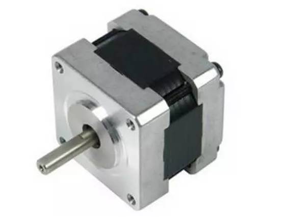
The stepper motor we generally use is like this:

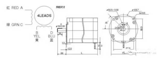
His structure diagram is generally like this:

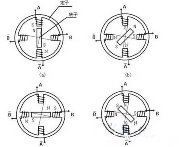
So what does this AC and BD stand for? Why does the stepper motor have the above characteristics? This starts with the special structure of the stepper motor. First, a schematic diagram of the internal structure of a stepper motor:

First analyze the principle from this simple diagram. In the diagram, there are two sets of windings A A- and B B-. It can be seen that the magnetic fields formed by them are opposite and their positions are relative. These 2 sets of windings correspond to AC and BD in the real picture.
The stator is an iron core. A A- and B B- are wound on the iron core. After energization, a magnetic field is generated to become an electromagnet. The rotor is a permanent magnet, and the magnetic field will attract or repel the rotor.
In the upper left picture, A A- attracts the rotor so that the rotor is vertical (only A A- is energized at this time). When B B- is also energized, B B- also generates a magnetic field. At this time, the rotation will deflect the middle area of the image AB. The specific deflection angle follows The current on AB is proportional to the magnitude.
In the lower left picture, when A A- is powered off and B B- continues to be energized, the rotor is attracted to the horizontal position.
In the lower right figure, A A- is energized in the reverse direction, B B- continues to be energized, then it will rotate clockwise, repeat the above process, the rotor can rotate, and the timing and sequence of energization can be controlled to control the stepper motor Rotation angle.
Stator core: The stator core is a salient pole structure and is made of laminated silicon steel sheets. There are small teeth with equal pitch on the surface of the stator core facing the air gap.


